


Views: 0 Author: Site Editor Publish Time: 2026-10-01 Origin: Site


In high-speed injection molding, the margin for error approaches zero. When cycle times drop below 3–4 seconds and dry cycle times are pushed to their absolute limits, any inconsistency in material preparation directly translates to scrap, machine downtime, and compromised unit economics. Achieving flow length to wall thickness (L/T) ratios of 200:1—and often up to 250:1 for modern food packaging—requires precise melt viscosity. Inadequate plastic material feeding leads to screw starvation and short shots, while improper drying introduces moisture that causes splay, structural weakness, and gate freeze-off in complex hot runner systems.
To maintain continuous, high-yield production, processors must evaluate and configure their feeding and drying infrastructure specifically for the aggressive throughput demands of Thin Wall Packaging Molding. This guide breaks down the technical criteria for specifying auxiliary setups that prevent bottlenecks, reduce energy consumption, and protect part integrity.
Throughput Matching is Critical: Feeding systems must be sized to handle rapid material consumption rates without causing bridging or starvation during sub-4-second cycle times.
Precision Drying Prevents Hydrolysis and Gate Issues: Even trace moisture in hygroscopic resins (or surface condensation on non-hygroscopic resins) alters melt flow index (MFI), destroying the tight tolerances required for thin-wall parts and causing high-cavitation gate freeze-off.
Auxiliary Integration Drives OEE: Synchronizing the plastic auto loader and hopper dryer with the primary injection molding machine and downstream automation (like robotic take-out) via closed-loop controls reduces energy waste and prevents material degradation.
Fines, Dust, and IML Compatibility: High-velocity conveying generates dust and static. Proper filtration and static mitigation are non-negotiable, especially when utilizing In-Mold Labeling (IML), where contamination ruins label adhesion and aesthetics.
Operating a thin-wall injection molding cell requires establishing a strict operational baseline. Success in this environment is defined by the ability to consistently fill cavities with flow length to wall thickness (L/T) ratios exceeding 200:1. Modern food containers often push this boundary to 250:1 to meet aggressive lightweighting goals. Achieving these ratios demands extreme injection speeds and pressures, often exceeding 30,000 psi (2,000 bar). At these velocities, the polymer melt experiences massive shear rates. The material must enter the barrel in a perfectly uniform state. Any fluctuation in pellet temperature, bulk density, or moisture content disrupts the plasticizing process. This disruption alters the melt flow index (MFI) shot-to-shot, making it impossible to maintain the tight dimensional tolerances required for stackable packaging and secure lid fitment.
Consider a 500ml deli container with a wall thickness of 0.35mm and a flow length of 85mm. The L/T ratio sits at approximately 242:1. To fill this cavity before the thin melt front freezes, the machine must inject the entire shot in under 0.1 seconds. If the material feeding system delivers pellets with varying moisture levels, the viscosity changes instantly. A sudden drop in viscosity causes the melt to flash across the parting line, damaging the mold steel. A sudden increase in viscosity results in short shots, leaving the container rim incomplete.
Standard auxiliary equipment sizing formulas routinely fail in thin-wall scenarios. The mathematical relationship between rapid shot consumption and material residence time dictates system design. Consider a 16-cavity mold producing polypropylene (PP) containers with a 3.5-second cycle time. If the shot weight is 150 grams, the machine consumes over 154 kilograms of resin per hour.
When calculating for continuous high-volume draw, the hopper must hold enough material to achieve the required drying or pre-heating time without creating dead zones. If the hopper is too small, the rapid drawdown reduces residence time, sending cold or wet pellets into the feed throat. If the hopper is too large, the material at the bottom may degrade from prolonged heat exposure. Processors must calculate the exact volumetric flow rate, factoring in the bulk density of the specific resin, to size the hopper for a precise first-in, first-out (FIFO) material flow.
Determine the maximum shot weight of the mold, including the runner system if applicable.
Identify the fastest possible cycle time the machine and automation can sustain.
Calculate the hourly material consumption rate in kilograms or pounds.
Divide the hourly consumption by the bulk density of the resin to find the volumetric draw rate.
Multiply the volumetric draw rate by the required drying time to determine the absolute minimum hopper capacity.
Temperature and moisture variations at the feeding stage directly alter the resin's flow behavior inside the barrel. Expert-engineered tooling relies on predictable melt viscosity to balance multi-cavity hot runner systems. When moisture causes hydrolysis in hygroscopic materials like PET, the polymer chains break down, resulting in a sudden drop in intrinsic viscosity (IV). This viscosity drop leads to uncontrolled flash across the parting line, damaging the mold and causing part rejection.
Conversely, if pellets enter the barrel too cold due to inadequate pre-heating, the screw must work harder to achieve the target melt temperature. This increases shear heating and risks degrading the polymer. Inconsistent viscosity also leads to short shots at the end of flow paths. In high-cavitation hot runners, highly viscous melt can cause gate drool or complete freeze-off. When a gate freezes in a 32-cavity mold, operators must halt production, pull the hot half, and clear the blocked drops manually, destroying overall equipment effectiveness (OEE).
Parameter | Standard Injection Molding | Thin Wall Packaging Molding | Impact on Material Preparation |
|---|---|---|---|
L/T Ratio | 50:1 to 100:1 | 200:1 to 250:1 | Requires absolute consistency in melt viscosity to prevent flash or short shots. |
Cycle Time | 15 - 30 seconds | 2.5 - 4.5 seconds | Demands ultra-fast material conveying and rapid receiver discharge. |
Injection Speed | Moderate | Extreme (up to 1000 mm/s) | High shear rates amplify any inconsistencies in pellet temperature or moisture. |
Material Draw | Intermittent | Continuous, high-volume | Requires precise hopper sizing to maintain exact residence times without dead zones. |
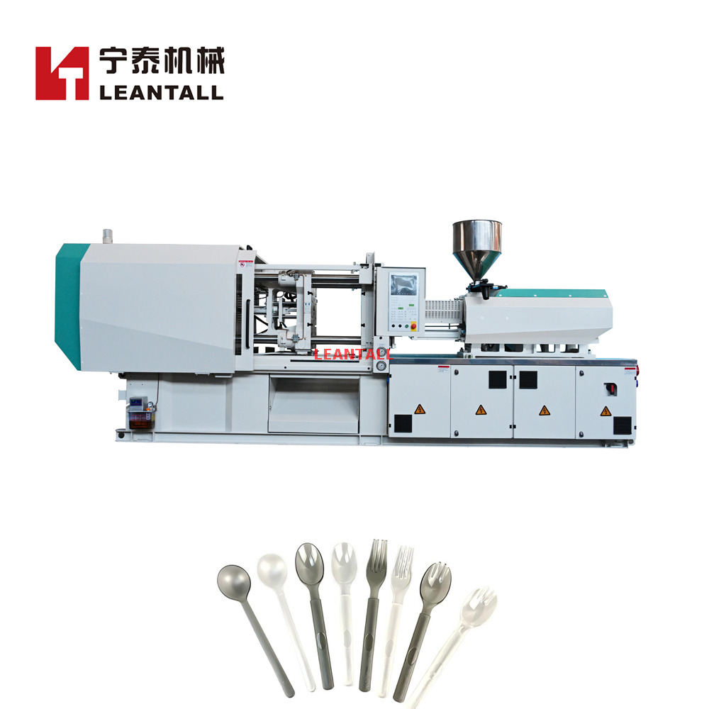
High-volume packaging lines generally utilize either centralized material handling systems or decentralized, press-side feeding setups. Centralized systems pump resin from outdoor silos to multiple machines via a network of vacuum pumps and manifolds. They excel in single-resin facilities but require complex manifold controls to prevent cross-contamination. Decentralized setups place dedicated vacuum loaders and dryers directly on or next to the molding machine. This approach offers maximum flexibility for custom packaging molders who frequently change resins, colors, or additives. For thin-wall applications, the physical distance between the material source and the feed throat must be minimized to prevent pellet degradation and dust generation during high-velocity transit.
When designing the conveying lines, pipe diameter and bend radius play a massive role in material integrity. Using undersized pipes increases the air velocity required to move the pellets. High-velocity conveying causes pellets to skid along the outside of pipe elbows, generating friction heat. This heat melts the surface of the pellets, leaving long, stringy residue known as "angel hair" or "snakeskins" inside the piping. Eventually, this residue breaks loose, clogs the receiver screens, and starves the molding machine. Upgrading to long-radius elbows with specialized surface treatments prevents this degradation.
Specifying a plastic auto loader for sub-4-second cycle times requires exact capacity calculations. You must determine the required conveying rate in kilograms per hour based on the maximum shot weight and the minimum cycle time. Furthermore, the loader must synchronize with robotic take-out systems. If a robot pauses the machine for 0.5 seconds to extract parts, the loader must account for this intermittent draw without overfilling or starving the receiver.
Motor and vacuum sizing dictate conveying efficiency. Regenerative blowers provide excellent performance for short-distance, press-side loading. However, for long-distance conveying from a central material room, positive displacement pumps (Roots blowers) are necessary. They generate higher vacuum levels to move large volumes of resin without increasing conveying velocity to a point where pellets shatter against pipe elbows. A properly sized vacuum system maintains a conveying velocity of roughly 4,000 to 4,500 feet per minute (FPM) for standard packaging resins.
Receiver design is equally critical. The geometry of the loader must ensure rapid, bridge-free discharge. Steep cone angles and oversized discharge flap valves allow pellets to dump instantly into the feed throat, keeping pace with ultra-fast screw recovery times. Capacitive sensors within the receiver must trigger the next fill cycle immediately to maintain a constant head pressure above the screw. If the head pressure fluctuates, the screw recovery time will vary, leading to inconsistent shot sizes and dimensional variations in the molded containers.
Thin-wall packaging operations generate significant regrind from skeletal webs (in thermoforming-injection hybrids) or rejected startup parts. Accurately dosing this in-line regrind alongside colorants requires precision blending. Volumetric blenders often struggle because the bulk density of regrind differs vastly from virgin pellets. Virgin PP pellets might have a bulk density of 0.55 g/cm³, while fluffy regrind can drop to 0.25 g/cm³. Gravimetric batch blenders weigh each component before mixing, ensuring exact ratios regardless of bulk density variations.
When dosing additives, the primary virgin feed rate must remain uninterrupted. Poorly mixed regrind introduces air pockets and varying melt densities into the barrel. In a 0.4mm thick container wall, a single unmelted flake of regrind or a poorly dispersed colorant pellet creates a stress concentrator. This weak point leads to structural failure during drop testing or stacking in the warehouse. Utilizing gravimetric blenders with specialized auger designs ensures homogeneous mixing before the material ever reaches the feed throat.
Selecting the correct drying technology depends heavily on the resin type and throughput. Desiccant wheel dryers provide a continuous, stable dew point by rotating a honeycomb rotor through drying and regeneration zones. Twin-tower desiccant dryers use two beds of desiccant beads, switching between them as one saturates. Compressed air dryers utilize plant air, expanding it to lower its dew point, making them suitable for smaller throughputs or press-side mounting. For high-volume thin-wall applications, continuous desiccant wheel technology is generally preferred because it eliminates the dew point spikes associated with twin-tower bed switchovers.
A hopper dryer must deliver consistent airflow to every pellet. If the airflow fluctuates, the thermal history of the pellets will vary. This variation changes the energy required by the screw to melt the plastic, leading to inconsistent melt temperatures and varying cavity pressures.
Hygroscopic materials like PET, commonly used for clear deli containers, absorb moisture internally. They require deep dew points (typically -40°C/-40°F) to extract moisture from within the pellet. Failure to achieve this results in severe IV drop and brittle parts. You can often see the results of wet PET visually; the parts will exhibit a yellowish tint and lose their optical clarity.
Non-hygroscopic materials like Polypropylene (PP) and Polystyrene (PS) do not absorb moisture internally. However, they frequently suffer from surface condensation, especially when moved from outdoor silos into warm, humid production floors. This surface moisture must be eliminated before plasticizing. If wet PP enters the barrel, the water flashes into steam, causing splay marks, reduced clarity, and compromised mechanical strength. Pre-heating these non-hygroscopic resins to around 80°C drives off surface moisture and normalizes the pellet temperature, stabilizing the plasticizing process.
Properly sizing the drying hopper requires balancing three variables: airflow, temperature, and dew point. The drying hopper must guarantee the exact required residence time. For example, PET requires approximately 4 to 6 hours of drying time. Over-drying PET by leaving it in the hopper for 10 hours causes thermal degradation, yellowing, and brittleness in the final thin-wall part.
Mass flow design is the foundation of effective drying. Hopper geometries must guarantee first-in, first-out (FIFO) material flow. If a hopper has shallow cone angles, material channels down the center, leaving stagnant pellets on the sides. These dead zones lead to uneven heating. The central pellets remain wet, while the perimeter pellets degrade from over-heating. A properly designed mass flow hopper ensures every pellet experiences the exact same thermal history before entering the feed throat. Installing a spreader cone at the base of the hopper helps distribute the heated air evenly across the entire material bed.
Resin Type | Moisture Behavior | Target Drying Temp | Target Dew Point | Required Residence Time | Risk of Improper Drying in Thin Wall |
|---|---|---|---|---|---|
PET | Hygroscopic | 150°C - 170°C | -40°C | 4 - 6 Hours | Severe IV drop, brittleness, yellowing, loss of optical clarity. |
Polypropylene (PP) | Non-Hygroscopic (Surface) | 80°C - 90°C | -20°C (Air Dry) | 1 - 2 Hours | Surface splay, steam voids, dimensional instability, flash. |
Polystyrene (PS) | Non-Hygroscopic (Surface) | 75°C - 85°C | -20°C (Air Dry) | 1 - 2 Hours | Silver streaks, gate blush, reduced impact resistance. |
PLA (Bioplastic) | Hygroscopic | 60°C - 80°C | -40°C | 2 - 4 Hours | Extreme viscosity loss, inability to pack out cavities, part sticking. |
Modern automated food packaging facilities demand strict adherence to FDA compliance and cleanroom standards. Every component touching the raw material must be constructed of polished stainless steel to prevent contamination and facilitate rapid washdowns. Scalability relies on selecting injection molding auxiliary equipment that can handle future throughput increases without requiring complete system overhauls. Modular drying systems and expandable vacuum manifolds allow processors to add capacity incrementally as cavitation increases.
When laying out a new production cell, engineers must account for the physical footprint of the auxiliary gear. Press-side equipment must not interfere with mold changes or robotic safety cages. Utilizing mezzanine structures to elevate dryers and blenders above the molding machine saves valuable floor space and allows gravity to assist in feeding the material directly into the machine throat.
Stand-alone auxiliary equipment creates information silos. Utilizing OPC UA or Euromap 82 protocols allows processors to sync the dryer and feeding system directly with the molding machine's PLC. This closed-loop communication enables dynamic scaling. If the injection molding machine halts due to a robotic take-out delay or a downstream packaging jam, the PLC signals the dryer to drop its temperature to a standby setpoint. This prevents the material from baking in the hopper. Once the machine resumes motion control, the dryer rapidly ramps back to the processing temperature, ensuring seamless material preparation without degradation.
Establish a physical or wireless network connection between the auxiliary PLC and the molding machine controller.
Map the data points using standardized Euromap 82.1 profiles for temperature control devices.
Configure alarm thresholds so that a material starvation event automatically pauses the injection cycle before a short shot occurs.
Set up automated temperature setbacks to protect resin integrity during unplanned machine downtime.
High-throughput material preparation consumes massive amounts of electricity. Analyzing the return on investment for variable frequency drives (VFDs) on conveying blowers and drying heaters is essential. VFDs adjust the motor speed based on actual demand rather than running at full capacity continuously. While continuous high throughput is necessary, over-spec'd equipment wastes energy. Implementing dew point control—where the dryer only regenerates the desiccant bed when the dew point rises above a specific threshold—targets the up to 50% lower energy consumption benchmarks demanded by modern, sustainable packaging facilities.
The first 90 days of thin-wall production expose every weakness in a material handling setup. Processors frequently encounter intermittent short shots, unexplained black specks, and erratic cycle times. These issues rarely stem from the molding machine itself; they almost always originate in the feeding and drying infrastructure. Identifying these failure points early prevents catastrophic mold damage and long-term yield losses.
Material starvation is a primary risk when cycle times dip below 3 seconds. The feed throat must remain completely full to maintain consistent screw recovery. However, high-speed screw rotation generates intense friction heat that travels up the barrel into the feed throat. If the throat cooling conditions are inadequate, pellets melt prematurely and fuse together, creating a bridge that blocks material flow. Mitigating this requires strict thermal management. The water flow rate and temperature at the feed throat casting must be precisely controlled to keep the metal surface below the resin's glass transition temperature (Tg), ensuring pellets remain solid until they enter the compression zone of the screw. Typically, feed throat water temperatures should be maintained between 40°C and 50°C.
High-speed vacuum conveying creates violent collisions between pellets and pipe walls. This degrades the pellets, generating dust and micro-fines.
The Risk: Fines melt much faster than whole pellets. They burn in the barrel, creating black specks that ruin the aesthetics of clear food packaging. Furthermore, dust settles on the mold surface. When utilizing In-Mold Labeling (IML), this dust creates surface defects that prevent the label from adhering properly, causing blistering and immediate part rejection.
The Mitigation: Specify cyclone dust separators at the receiver inlet to pull fines out of the material stream before they enter the hopper. Install inline filters on the vacuum lines and utilize closed-loop conveying air filtration to prevent dust from escaping into the cleanroom environment.
Friction during conveying generates severe static electricity. Static causes material to cling to the hopper walls, disrupting FIFO flow and causing false readings on capacitive level sensors. In thin-wall molding, static is particularly destructive to automated IML insertion processes. If the molded part carries a static charge from the material handling phase, the robotic arm will struggle to place the label accurately inside the cavity. Addressing this requires installing static elimination bars in the conveying lines and ensuring all metal piping is properly grounded to dissipate the charge before the material reaches the machine.
Symptom | Root Cause in Material Handling | Immediate Corrective Action |
|---|---|---|
Black specks in clear parts | Fines burning in the barrel or degraded material in hopper dead zones. | Clean cyclone separators; verify hopper mass flow geometry. |
Inconsistent screw recovery time | Material bridging in feed throat or fluctuating head pressure. | Check feed throat cooling water flow; verify loader sensor placement. |
IML label blistering | Dust contamination or static charge on the molded part. | Inspect inline filters; verify grounding on all conveying lines. |
Flash on parting line | Viscosity drop due to wet resin (hydrolysis). | Check dryer dew point sensor calibration; verify residence time. |
Successful thin wall packaging molding relies entirely on a highly calibrated, high-throughput material preparation phase. The primary molding machine and downstream automation can only perform as well as the material they receive. Any fluctuation in moisture, temperature, or feed rate destroys the delicate balance required to fill ultra-thin cavities at extreme speeds. When selecting equipment, prioritize auxiliary vendors who offer performance guarantees based on specific cycle times, L/T ratios, and energy efficiency metrics, rather than generic capacity ratings. A system sized correctly for standard molding will fail under the continuous, aggressive draw of a thin-wall packaging cell.
Conduct a comprehensive material flow audit to identify current bottlenecks in your conveying lines and drying hoppers.
Calculate exact volumetric throughput requirements based on the fastest projected cycle times and maximum cavitation of your tooling.
Request pilot testing for hygroscopic packaging resins to verify dew point stability and IV retention under continuous draw.
Implement closed-loop communication protocols between your auxiliary equipment and the primary molding machine PLC.
Upgrade feed throat cooling circuits to prevent bridging during high-speed, high-friction screw recovery.
A: Polypropylene (PP) is non-hygroscopic but requires drying to remove surface condensation. The ideal residence time is typically 1 to 2 hours at 80°C to 90°C. Over-drying provides no benefit and wastes energy, while under-drying allows surface moisture to enter the barrel, causing steam voids and flash in thin-wall parts.
A: It relies on oversized discharge flap valves, steep receiver cone angles, and highly responsive capacitive sensors. The loader must be sized to convey material faster than the machine's consumption rate, ensuring the feed throat remains fully packed even during intermittent pauses for robotic part extraction.
A: Yes. While PP does not absorb moisture internally, temperature differentials between storage silos and the production floor cause surface condensation. In high-speed thin-wall molding, this surface water flashes into steam inside the barrel, altering the melt flow front and causing visual defects or short shots.
A: Bridging occurs when high-speed screw rotation generates friction heat that travels up the feed throat, causing pellets to melt prematurely and stick together. Strict cooling conditions—using dedicated water circuits to keep the throat casting below the resin's glass transition temperature—prevent pellets from melting before entering the screw.
A: Do not use standard formulas. Calculate the exact kilograms per hour based on the maximum shot weight and the absolute minimum cycle time. Size the hopper to guarantee the exact required residence time for that specific throughput, ensuring first-in, first-out (FIFO) mass flow without dead zones.
A: Clear packaging often uses hygroscopic resins like PET, which absorb internal moisture. Hot air dryers only remove surface moisture. Desiccant dryers generate ultra-dry air (down to -40°C dew point) to extract internal moisture, preventing hydrolysis, loss of intrinsic viscosity (IV), and yellowing in the final part.
A: High-speed conveying creates dust and static. Dust burns in the barrel, causing black specks, and settles on the mold, preventing IML labels from adhering properly. Static electricity disrupts the robotic insertion of labels and causes pellets to cling to hopper walls, disrupting material flow and sensor accuracy.


