


Views: 0 Author: Site Editor Publish Time: 2026-09-01 Origin: Site


In the high-volume production of thin wall plastic products, profitability is dictated by fractions of a second and absolute consistency. Standard injection molding equipment cannot overcome the rapid melt-freezing and extreme pressure drops inherent in high flow-path to wall-thickness ratios. This limitation leads to short shots, flashing, and unacceptable cycle times on the production floor. Selecting the correct equipment requires moving beyond basic tonnage ratings. You must evaluate the three defining metrics of high-speed molding: injection velocity, accumulator capacity, and system repeatability. Mastering these factors ensures sustainable, short-cycle production without premature equipment failure. We will break down the mechanics of thin-wall applications and match machine specifications to tooling requirements. You will learn how to evaluate drive technologies, structural necessities, and automation integration to optimize your manufacturing floor.
Velocity Overcomes Viscosity: Thin wall injection molding requires specialized machines capable of extreme injection speeds (often exceeding 500 mm/s) to fill cavities before the polymer freezes.
Structural Integrity is Non-Negotiable: High-speed injection generates immense cavity pressure; reinforced platens and robust tie-bar designs are mandatory to prevent mold deflection and flashing.
Repeatability Equals Profitability: Raw speed is useless without millisecond-level response times to guarantee shot-to-shot consistency across millions of cycles.
Drive Technology Dictates TCO: Choosing between an all-electric, hybrid, or servo injection molding machine fundamentally impacts energy consumption, precision, and long-term maintenance costs.
System-Level Integration: A high speed injection molding machine must be evaluated alongside its compatibility with high-performance multi-cavity molds, advanced venting, and high-speed automation like In-Mold Labeling (IML).
Understanding the physical demands of thin-wall parts is the first step in equipment selection. The industry defines a part as "thin-wall" based on two primary metrics. The first is an absolute wall thickness of less than 1mm. The second, and more critical, is the flow-path to wall-thickness ratio (L/t ratio). Standard molding typically involves L/t ratios around 100:1. In contrast, thin wall injection molding frequently pushes this ratio beyond 150:1, sometimes reaching 300:1 for specialized packaging.
To calculate the L/t ratio, you measure the distance from the gate to the furthest point in the cavity and divide it by the average wall thickness. For example, a container with a 0.4mm wall thickness and a 120mm flow length has an L/t ratio of 300:1. Pushing molten polymer through such a restrictive space requires immense force and speed. Rigid food packaging relies heavily on this technology. Products like yogurt cups, margarine tubs, and 1L pails require minimal material usage to maintain margins. Medical disposables represent another massive application area. Syringes, pipettes, and specimen containers demand extremely thin walls combined with flawless optical clarity.
The physics of filling these parts presents a severe challenge known as the fountain flow effect. As molten polymer enters a cold mold cavity, the material touching the steel walls freezes instantly. This creates a frozen layer that constricts the already narrow flow channel. In thin-wall parts, this freezing happens in milliseconds. If the injection speed is too slow, the core melt freezes completely before the cavity is full, resulting in a short shot. Rapid injection utilizes shear heating to keep the polymer flowing. High velocity generates internal friction within the plastic, temporarily lowering its viscosity and delaying the freeze-off point.
Standard hydraulic machines fail in these applications due to fundamental design limitations. Conventional pumps cannot deliver the massive volume of hydraulic oil required for sub-second injection times. Standard machines lack the necessary specific injection pressure. Pushing high-viscosity melts through restrictive gates requires immense force. Standard controllers cannot process signals fast enough to execute the rapid deceleration needed at the end of the injection stroke. This leads to overpacking, mold damage, and severe flashing.
Parameter |
Standard Injection Molding |
Thin Wall Injection Molding |
|---|---|---|
L/t Ratio |
Up to 100:1 |
150:1 to 300:1 |
Injection Speed |
50 - 150 mm/s |
300 - 800+ mm/s |
Specific Injection Pressure |
1,000 - 1,500 bar |
2,000 - 3,000+ bar |
Fill Time |
1.0 - 3.0 seconds |
0.1 - 0.5 seconds |
Controller Scan Time |
2 - 5 milliseconds |
< 1 millisecond |
Velocity is the defining characteristic of a High Speed Injection Molding Machine. Standard machines typically inject at speeds between 100 and 150 mm/s. Thin-wall applications demand benchmark speeds starting at 300 mm/s. High-performance packaging often requires speeds exceeding 500 mm/s, and sometimes up to 800 mm/s. Achieving these velocities requires specialized hydraulic architecture that standard variable displacement pumps cannot provide.
Nitrogen accumulators are mandatory for high-speed hydraulic and hybrid machines. An accumulator acts as a massive energy storage device. During the cooling phase, the machine's pumps compress nitrogen gas behind a piston or bladder filled with hydraulic oil. When the injection phase begins, a high-response proportional valve opens. The compressed nitrogen expands instantly, driving the oil into the injection cylinders at a rate far exceeding the pump's standalone capacity. Piston accumulators are generally preferred for extreme speeds because they offer faster discharge rates than bladder types.
Speed alone is insufficient without adequate pressure. High specific injection pressure is required to overcome the resistance of thin cavities. Standard machines max out around 1,500 bar. High-speed machines must generate specific injection pressures between 2,000 and 3,000 bar. This immense pressure ensures the melt front maintains its velocity through the entire flow path, preventing hesitation and premature freezing. If the machine hits its pressure limit before the cavity is full, the injection speed will drop, leading to a short shot.
Raw speed and extreme pressure create a volatile process. Controlling this volatility requires ultra-fast controller response times. When injecting at 500 mm/s, a mold cavity fills in less than a tenth of a second. The machine must switch from velocity control to pressure control (V/P switchover) at the exact moment the cavity is 95% to 98% full. High-end machines utilize Moog servo valves or highly responsive proportional directional valves to execute this switchover.
If the controller delays this switchover by just a few milliseconds, the machine will ram high-pressure plastic into a full cavity. This causes severe flashing and can permanently damage the mold steel by hobbing the core into the cavity block. Conversely, switching over too early results in short shots and sink marks. High-speed controllers operate with scan times of 1 millisecond or less. This ensures the valves react instantly to position or pressure sensors.
Setting up a reliable V/P switchover on a high-speed machine requires a systematic approach:
Set the holding pressure to zero and the holding time to zero.
Set the injection speed to the target velocity required to prevent freezing.
Gradually increase the shot size or adjust the switchover position until the part is 95% full.
Monitor the peak injection pressure to ensure the machine is not hitting its pressure limit.
Introduce holding pressure to pack out the remaining 5% of the cavity and eliminate sink marks.
Rapid injection creates massive spikes in cavity pressure. The clamping unit must hold the mold closed against this explosive force. Thin-wall parts require significantly higher clamping tonnage per square inch of projected area compared to standard parts. A highly responsive clamping system is necessary to build and maintain this force instantly. Toggle clamp designs are heavily favored in high-speed applications because they provide rapid lock-up speeds and mechanical advantage.
Platen deflection is a silent killer in high-speed operations. When immense injection pressure hits the center of the mold, the machine platens can bow outward. Even microscopic deflection allows plastic to escape the cavity, creating flash around the parting line. Reinforced, high-rigidity platens are absolute necessities. They maintain parallel alignment under extreme stress, protecting the tooling and ensuring part quality. Platen parallelism should be maintained within 0.05mm across the entire face under full tonnage.
Tie-bar design dictates how clamping force is distributed across the mold surface. Advanced high-speed machines utilize optimized tie-bar spacing and robust casting designs. This ensures even force distribution, which is especially critical for balancing flow in high-cavitation tooling. When running a 32-cavity or 64-cavity mold, uneven clamping force causes the center cavities to flash while the outer cavities short-shot. Tie-bar strain gauges are often integrated into the machine controller to monitor and auto-adjust clamping force distribution.
Short cycle times demand high-throughput plasticizing. The machine must melt the next shot of plastic while the current part is cooling. Standard screws often struggle to melt resin fast enough without introducing excessive shear heat. This leads to material degradation, burning, and weak parts. The screw must deliver a homogeneous melt at high recovery rates.
Specialized screw designs are required. Barrier screws with an L/D (Length to Diameter) ratio of 25:1 or 30:1 are commonly used in high-speed applications. They feature a secondary flight that separates melted polymer from unmelted pellets. This increases melting efficiency and ensures a consistent melt temperature at high RPMs. Mixing heads are also utilized to ensure consistent color dispersion during rapid plasticizing.
Simultaneous movements are critical for shaving tenths of a second off the cycle time. Independent drives allow the machine to rotate the screw and build the next shot while the mold is opening and ejecting the previous part. This overlapping of machine functions is a primary driver of cycle time reduction in modern high-speed equipment. Without simultaneous movements, the machine must wait for the mold to close before starting the plasticizing phase, adding seconds to the overall cycle.
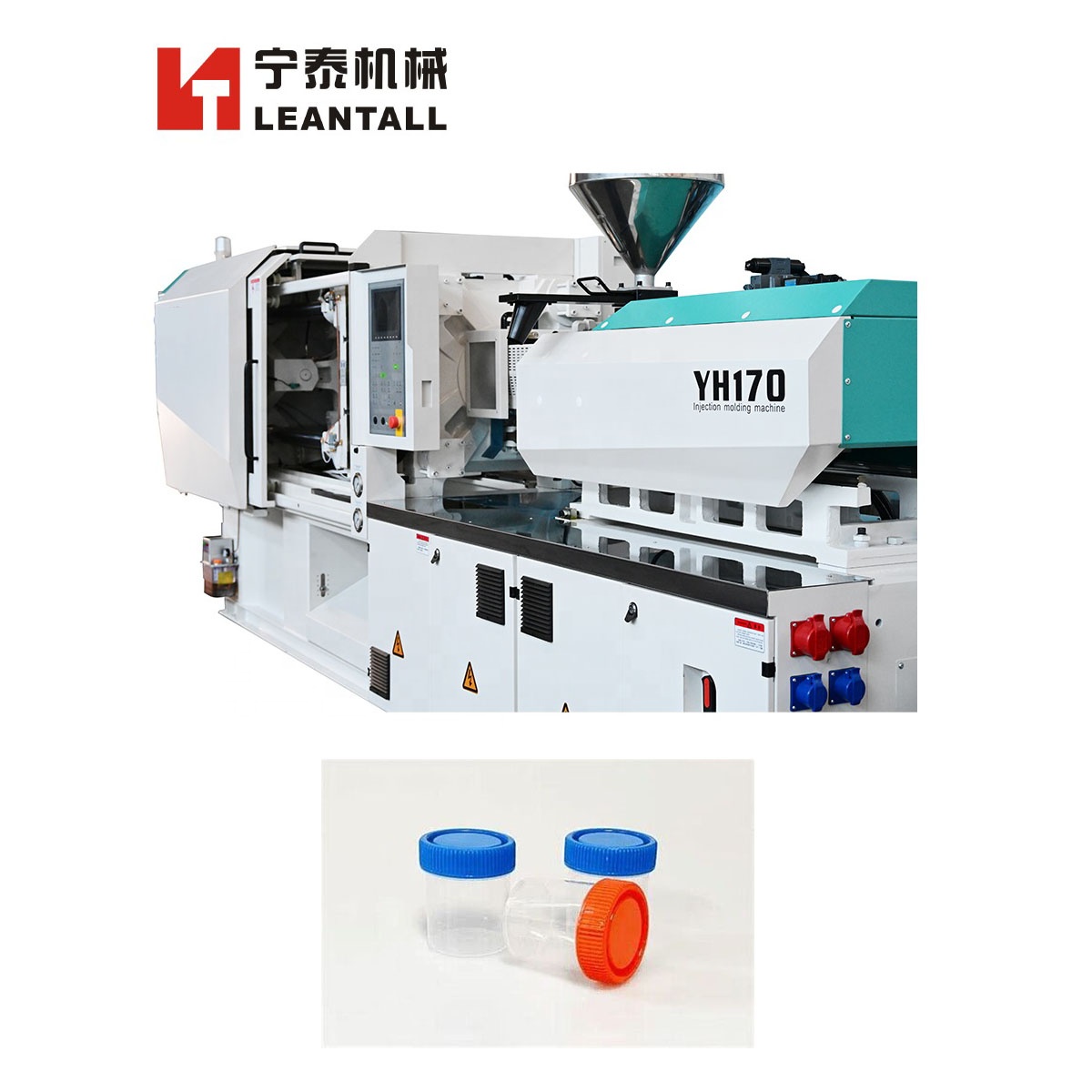
A servo injection molding machine represents a massive leap over traditional fixed-pump hydraulic systems. Instead of running a motor constantly at full speed, a servo-hydraulic system uses variable speed permanent magnet synchronous motors (PMSM) to drive internal gear pumps. The motor only spins when the machine requires hydraulic flow or pressure. During the cooling phase, the motor virtually stops.
This mechanism provides an excellent balance of high injection power and energy efficiency. Servo systems can still utilize accumulators to achieve the extreme speeds required for thin-wall parts. They offer significantly faster response times than traditional variable displacement pumps. The primary advantage is lower capital expenditure compared to fully electric models, while still delivering the brute force necessary for large, thin-wall containers.
Hybrid machines combine the best elements of electric and hydraulic technologies. The most common architecture utilizes electric drives for mold opening/closing and screw rotation. Meanwhile, an accumulator-driven hydraulic system powers the injection axis. This isolates the high-speed, high-force requirement of injection from the precision requirements of clamping and melting.
Hybrids are widely considered the industry standard for extreme thin-wall packaging. Molding dual-cavity 1L pails with reduced wall thickness requires massive injection volume and speed. Electric injection motors often struggle to match the instantaneous power delivery of a hydraulic accumulator. The hybrid design offers the raw power of hydraulics for injection, paired with the precision, simultaneous movement capability, and energy savings of electric drives for all other axes.
Fully electric machines utilize direct-drive servo motors and heavy-duty roller screws for every machine movement. They eliminate hydraulic oil entirely. This architecture provides unmatched shot-to-shot consistency. Electric drives offer absolute positional accuracy, making them ideal for precise V/P switchovers. They are also the most energy-efficient option and are inherently cleanroom compatible due to the absence of oil leaks.
Historically, electric machines faced limitations in thin-wall applications. The ball screws and motors struggled to generate the absolute highest injection speeds and sustained peak pressures without suffering premature wear. Modern direct-drive technologies and roller screw designs are closing this gap. High-speed electric machines are now highly effective for specific medical disposables, electronic housings, and smaller packaging items where precision outweighs raw injection volume.
When upgrading to a high speed injection molding machine, evaluating production efficiency requires looking at yield metrics and energy consumption. Energy usage is typically measured in kilowatt-hours per kilogram of processed material (kWh/kg). Standard hydraulic machines often consume around 0.7 kWh/kg. Servo-hydraulic machines reduce this to approximately 0.4 kWh/kg. All-electric machines offer the highest efficiency, often dropping below 0.25 kWh/kg. Over a multi-year production run, these energy savings heavily influence the equipment's return on investment.
Cycle time reduction directly impacts annual part yield. Shaving just 0.5 seconds off a 4.0-second cycle time increases production output by over 14%. This increased yield allows manufacturers to fulfill larger orders without adding additional machine cells to the floor. You must calculate the increased revenue generated by the higher part yield against the initial capital expenditure of the high-speed equipment.
Machine lifespan and maintenance schedules differ significantly in high-speed operations. The accelerated wear and tear inherent in sub-second cycles requires rigorous maintenance. Hydraulic oil must be filtered to 3 microns to protect sensitive servo valves. Linear guides and toggle pins require automated, high-frequency lubrication systems. Evaluating the durability of the machine's castings and the availability of spare parts is critical for maintaining high uptime over a ten-year operational lifespan.
A high-speed machine is only as effective as the mold it operates. Subjecting a standard mold to high-speed injection will destroy the tooling. The immense cavity pressures require high-hardness steels, typically H13 or Stavax, hardened to 50-54 HRC. Core shift is a major risk in thin-wall parts like cups and pails. The mold must feature robust interlocking mechanisms to keep the core perfectly centered during the high-pressure injection phase.
Cooling is another critical tooling factor. Thin-wall parts cool rapidly, but the mold steel absorbs massive amounts of heat due to the short cycle times. Conformal cooling channels, often manufactured via 3D metal printing, are necessary to extract heat evenly and rapidly. Beryllium copper inserts are frequently used in core caps to pull heat away from hard-to-reach areas. Perfectly balanced hot runners are mandatory to ensure all cavities fill simultaneously.
Advanced venting is a strict requirement. When plastic is injected at 500 mm/s, the air inside the cavity must escape instantly. If the air is trapped, it compresses and superheats, causing the diesel effect. This burns the plastic and damages the mold steel. Precision venting channels, typically 0.02mm deep for polypropylene, must be machined around the entire parting line. Active vacuum assistance is often required to evacuate air rapidly ahead of the melt front.
High-speed production relies heavily on automation. In-Mold Labeling (IML) is standard for thin wall plastic products like food containers. IML requires exact synchronization between the machine's core sequences and high-speed side-entry robots. The robot must enter the open mold, place the label using static pinning wands, remove the finished part, and exit in under 0.8 seconds. If the robot intervention time is slow, it negates the speed advantages of the injection machine.
Ejection and part handling present unique challenges. Thin-wall parts are fragile while still warm. Standard ejector pins can easily punch through the plastic or cause severe deformation. High-speed, precise ejection systems are required. These often utilize a combination of air blasts to break the vacuum seal and multi-stage stripper plates to remove the part evenly without localized stress. The robot end-of-arm tooling (EOAT) must use high-flow vacuum cups to grip the parts securely without crushing them.
Thin wall injection molding operates within a very narrow process window. A change in melt temperature of just a few degrees, or a shift in switchover position by a fraction of a millimeter, will result in scrap. Standard molding techniques do not apply here. Operators cannot simply increase pressure to fix a short shot, as this will immediately cause flashing and tool damage.
Advanced controller interfaces are required to monitor the process. Technicians must be highly trained to interpret injection pressure curves and velocity profiles. They must understand how to adjust the V/P switchover point based on real-time cavity pressure data. Investing in high-speed equipment necessitates an equal investment in workforce training to ensure the machinery operates at its designed capacity. Process engineers must rely on data-driven adjustments rather than trial and error.
Investing in high-speed injection molding equipment is a system-level decision requiring strict alignment between machine specifications, mold design, and automation capabilities. Raw speed must be balanced with structural rigidity and precise control to maintain profitability. To ensure a successful implementation, follow these actionable steps:
Calculate your specific flow-path to wall-thickness ratios and target cycle times before requesting machine specifications.
Conduct a physical mold trial on a prospective machine to verify fill rates and platen deflection under actual production loads.
Verify accumulator capacity, specific injection pressure limits, and controller response times directly with the equipment manufacturer.
Align your machine selection with your existing automation, ensuring robot intervention times do not bottleneck the overall cycle.
Request comprehensive performance calculations from the OEM to validate energy consumption and cycle time reductions.
A: A high-speed machine is defined by three core metrics: injection velocity typically exceeding 300 to 500 mm/s, the integration of accumulators to deliver instantaneous high pressure and volume, and reinforced structural rigidity paired with millisecond-level controller response times to handle extreme cavity pressures.
A: While standard molding operates around a 100:1 ratio, thin-wall applications typically exceed 150:1. Depending on the polymer's melt flow index and the machine's injection capabilities, specialized packaging can push this ratio up to 300:1.
A: Servo machines improve cycle times through rapid motor response and the ability to execute simultaneous movements. Independent servo drives allow the machine to plasticize the next shot while the mold is simultaneously opening and ejecting the current part, saving critical fractions of a second.
A: Accumulators store pressurized hydraulic fluid and nitrogen gas. They release this energy instantly during the injection phase, providing a massive burst of hydraulic flow that standard pumps cannot match. This extreme speed is necessary to fill thin cavities before the polymer freezes.
A: Thin-wall parts require significantly higher clamping tonnage per square inch of projected area compared to standard parts. The extreme injection pressures required to force high-viscosity melt through thin sections create massive cavity pressure, demanding robust clamping force to prevent mold deflection and flashing.
A: No. Subjecting standard molds to high-speed processes risks severe mold deflection, inadequate cooling, and poor venting. The extreme pressures will cause standard steel to fatigue, resulting in severe flashing, core shift, and permanent damage to the tooling.


