


Views: 0 Author: Site Editor Publish Time: 2026-09-25 Origin: Site


Producing thin wall packaging creates a fundamental engineering conflict on the shop floor. Processors must achieve high-speed, high-pressure injection to fill narrow cavities before the melt freezes. Simultaneously, they must maintain absolute mold integrity and precise part dimensions. When pushing cycle times to their limits, operators frequently encounter flash, short shots, weak weld lines, or premature mold wear. The standard reaction is to increase clamping tonnage. This approach treats the symptom while ignoring the root cause. Most of these defects stem from poor platen design and structural deflection under peak cavity pressure, not a lack of raw force.
Evaluating a Thin Wall Molding Machine requires looking beyond the tonnage rating on the spec sheet. Assessing structural clamping rigidity and precision opening control provides a far more reliable predictor of long-term OEE and part quality than raw clamping force alone. A machine built with a rigid frame and optimized platens absorbs the massive shockwaves of high-speed injection without bending. This structural stability keeps the mold parting line perfectly sealed, allows for proper gas venting, and protects expensive tooling from fatigue. Understanding how rigidity dictates output is the first step toward stabilizing your high-speed molding process.
Rigidity Over Raw Tonnage: A high-rigidity injection molding machine allows for lower overall clamping force, which improves gas venting and reduces mold wear.
Defect Prevention: Even microscopic platen deflection under high injection pressure causes uneven force distribution, leading directly to flash, weak weld lines, and dimensional inconsistencies.
Asset Protection: Superior clamping rigidity prevents mold misalignment and tie bar breakage, drastically reducing unplanned downtime and maintenance costs.
Cycle Time Optimization: Stable clamping mechanisms and precise opening control enable faster, more consistent mold kinematics, maximizing hourly output.
When extreme injection pressure hits the mold cavity, the physical forces transfer directly to the machine's clamping unit. The stationary and moving platens act as the primary defense against this outward pressure. The melt tries to force the mold halves apart. Because the mold sits in the center of the platens, the injection force concentrates there. The machine applies counter-force through the tie bars located at the four corners. This creates a bending moment. The center of the platen wants to bow outward while the corners remain pulled tight.
If the machine lacks sufficient clamping rigidity, this bending moment causes platen deflection. The mold halves separate microscopically at the center. At the same time, the tie bars stretch under the load. Steel is elastic, and under hundreds of tons of force, tie bars stretch like heavy springs. If the platens deflect unevenly, the tie bars stretch unevenly. This transfers unequal stress to the mold and the machine frame. High rigidity counteracts this natural tendency. Thick, well-engineered platens resist bowing. They keep the parting line parallel and distribute the clamping load evenly across the entire mold face.
Filling a thin wall part requires overcoming immense flow resistance. The plastic melt cools and thickens the millisecond it touches the cold mold steel. To prevent the material from freezing before the cavity fills, the machine must inject the plastic at extreme velocities. This rapid injection creates a massive spike in cavity pressure right at the end of the fill phase, often exceeding 25,000 PSI inside the tool.
This pressure spike acts like a hammer blow against the mold and the platens. Standard machines absorb this blow poorly. The platens flex, the mold breathes, and the clamping mechanism shudders. A rigid machine absorbs this kinetic energy without losing dimensional stability. The platens remain flat. The toggle mechanism or hydraulic ram holds firm. This mechanical stiffness ensures that the volume of the mold cavity remains constant during the pressure spike, which dictates part weight and dimensional accuracy.
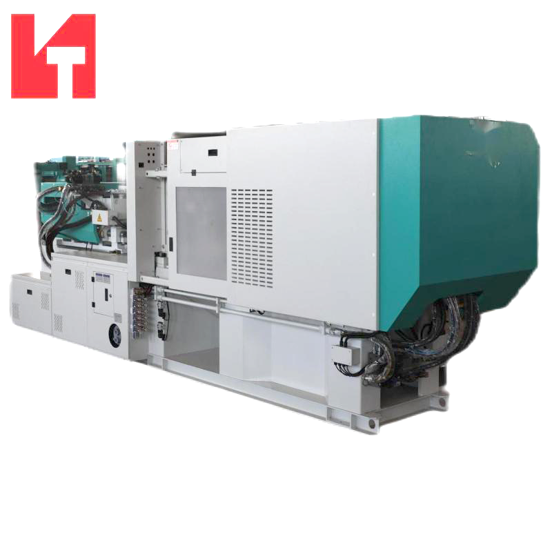
The severity of the injection process scales with the part's flow length to wall thickness (L/t) ratio. Standard molding might see L/t ratios of 50:1 or 100:1. Modern thin wall molding routinely pushes past 200:1 or even 300:1. The wall thickness often drops below 0.4 millimeters. Pushing viscous polymer through such a restrictive gap requires extraordinary force. The material must flow fast enough to generate shear heating, which keeps the melt fluid until the cavity is completely packed.
This dynamic creates a hostile environment for the clamping unit. The injection unit must deliver maximum pressure instantly. The clamping unit must resist that pressure just as fast. Any structural weakness in the machine frame or platens will manifest as a process variation. If the platen yields even a fraction of a millimeter, the effective wall thickness of the part increases. This changes the flow dynamics, alters the cooling rate, and ruins the part's structural integrity.
To achieve the necessary injection speeds, thin wall machines rely on hydraulic accumulators. These devices store hydraulic energy using compressed nitrogen and release it in a fraction of a second. This allows the injection ram to reach velocities exceeding 800 millimeters per second. The resulting deceleration at the end of the stroke transfers massive kinetic energy into the mold.
A machine lacking structural integrity will vibrate and flex under this load. This vibration disrupts the packing phase. The clamping unit must possess the mass and stiffness to deaden these vibrations instantly. High structural integrity ensures that the transition from velocity control to pressure control happens smoothly, without the platens bouncing or the mold shifting laterally on the guide pins.
Flash is the most common enemy in high-speed packaging production. It occurs when plastic escapes the mold cavity and flows across the parting line. Processors often assume flash means the machine lacks enough tonnage. In reality, flash usually indicates platen deflection. When the center of the platen bows outward, the clamping force at the center of the mold drops to zero. The injection pressure easily forces the mold halves apart at that specific location.
A high-rigidity injection molding machine solves this mechanically. By keeping the platen face flat under maximum load, the machine maintains uniform pressure across the entire parting line. The mold stays shut, and the plastic stays in the cavity. This eliminates the need for manual trimming, prevents automated stacking systems from jamming, and ensures a clean, professional finish on the final product.
When plastic flows around an obstacle in the mold, the flow fronts must meet and fuse together. This fusion creates a weld line. In thin wall parts, weld lines are inherently weak because the material is already cooling rapidly. If the platen deflects during injection, the cavity volume expands slightly. This expansion causes a sudden drop in melt pressure right when the flow fronts are trying to fuse.
The result is a weak weld line that will fail under stress. Furthermore, a breathing mold creates parts with inconsistent wall thickness. A container might be thicker on one side than the other, causing it to warp during cooling or fail during top-load testing. Rigid clamping maintains consistent cavity pressure, ensuring strong weld lines and uniform dimensions across every cycle.
When operators see flash, their immediate reaction is to increase the injection molding clamping force. This creates a cascading series of failures. Molds are designed with microscopic vents on the parting line, often only 0.02mm deep for materials like polypropylene. These vents allow air to escape as the plastic rushes in. If you apply excessive tonnage to a mold sitting on a flexing platen, you crush the edges of the mold while trying to force the center closed.
Crushing the edges pinches off the vents. The air inside the cavity has nowhere to go. It compresses rapidly, superheats, and burns the plastic. This phenomenon, known as dieseling, leaves black burn marks on the parts and damages the mold steel. High rigidity allows you to run the process at lower tonnage. The platens stay flat, the mold closes evenly, and the vents remain open.
Excessive clamping force destroys expensive tooling. When a machine flexes and operators crank up the tonnage to compensate, the mold absorbs the abuse. The constant over-compression causes the parting line to coin. The steel actually deforms over time, creating a permanent gap. Once a mold is coined, it will flash regardless of how much tonnage you apply.
Furthermore, uneven platen deflection forces the mold guide pins and bushings to handle loads they were not designed for. The mold halves try to shift laterally, causing severe wear on the alignment components. A rigid machine frame protects your tooling investment. It ensures the mold opens and closes perfectly parallel, extending the life of the mold by millions of cycles.
Platen deflection doesn't just damage the mold; it destroys the machine. When a platen bows, the tie bars stretch unevenly. The inner fibers of the tie bars experience much higher stress than the outer fibers. This uneven loading creates bending stresses within the steel.
Over millions of high-speed cycles, these bending stresses cause metal fatigue. Micro-cracks form in the threads of the tie bars. Eventually, a tie bar will snap violently during a cycle. Replacing a broken tie bar causes massive unplanned downtime and incurs heavy repair costs. Investing in structural rigidity ensures the clamping load remains purely axial, protecting the tie bars from fatigue and preventing catastrophic failure.
Profitable thin wall production relies on shaving fractions of a second off the cycle time. The mold must open, eject the part, and close as fast as physically possible. This requires aggressive acceleration and deceleration profiles. A flimsy machine frame cannot handle these violent movements. It will shake and vibrate, requiring the operator to slow down the mold movements to prevent damage.
A rigid machine frame acts like a solid anchor. It absorbs the kinetic energy of the moving platen. This allows you to program aggressive speed profiles. The mold can slam shut and brake at the very last millimeter without shuddering. Reducing the settling time—the time it takes for the machine to stop vibrating before it can lock up and inject—directly reduces the overall cycle time.
Fast cycles require flawless part ejection. If the mold opens unevenly, the parts can stick to the cavity or get damaged by the ejector pins. High rigidity ensures the moving platen remains perfectly parallel to the stationary platen during the entire opening stroke.
This precision opening control allows for exact positioning. The robot or free-fall system can rely on the parts being in the exact same location every single cycle. Consistent ejection prevents parts from hanging up in the mold, which would otherwise trigger mold protection alarms and halt production. Maximizing output means keeping the machine running continuously, and stable kinematics are essential for uninterrupted operation.
You can often diagnose a machine's rigidity issues simply by examining the parts it produces. Flash patterns tell a clear story. If a part flashes exclusively in the center of the mold, but the edges are clean, you are witnessing platen deflection. The center of the platen is bowing outward, allowing the mold to separate.
Conversely, if you see flash on the outer edges of the mold, but the center is clean, the mold itself might be bowing, or the platens are wrapping around a mold that is too small for the machine. Understanding these patterns allows technicians to stop chasing process variables like melt temperature or injection speed, and focus on the mechanical reality of the clamping unit.
To quantify platen deflection, technicians use magnetic dial indicators. This provides concrete data regarding how much the machine flexes under load. Follow this procedure to measure deflection accurately:
Mount the magnetic base of the dial indicator securely onto the stationary machine frame.
Position the indicator tip against the center back of the moving platen.
Close the mold and build full clamping tonnage, then zero out the dial indicator.
Run a standard production cycle and observe the dial during the injection pressure spike.
Record the maximum movement. Deflection exceeding a few thousandths of an inch indicates a lack of structural rigidity.
Not all cast iron is created equal. The structural integrity of a platen depends heavily on its design and material composition. Modern machine builders use Finite Element Analysis (FEA) to simulate the stresses of injection. This software dictates where the platen needs more mass and where material can be removed to save weight.
Look for machines with box-type platen designs. These feature deep ribs cast into the back of the platen. The ribbing pattern usually radiates from the center outward, specifically engineered to counteract the bending moment caused by the mold. A well-designed platen will maintain a flat face even when subjected to maximum injection pressure.
The type of clamping mechanism also influences rigidity. Five-point double toggle systems are the standard for high-speed packaging. When a toggle mechanism locks over center, it creates a rigid mechanical lock. The stiffness of this lock depends on the mass of the toggle links and the diameter of the pins.
Direct hydraulic clamping machines apply force via a large ram behind the moving platen. While hydraulic machines offer excellent force distribution, the column of hydraulic oil can compress slightly under peak injection pressure. For the absolute fastest cycle times and highest resistance to cavity pressure spikes, heavy-duty toggle mechanisms generally provide superior mechanical stiffness.
Advanced machines incorporate strain gauges directly into the tie bars. These sensors monitor the stretch of each individual tie bar in real-time. If the machine detects that one tie bar is stretching more than the others, it indicates an unbalanced load.
Some systems can automatically adjust the tie bar nuts to compensate for this imbalance, ensuring perfectly even force distribution. This technology compensates for slight variations in mold parallelism and thermal expansion, guaranteeing that the clamping force remains perfectly distributed across the mold face cycle after cycle.
Understanding the operational differences between standard machines and those engineered specifically for high-speed, thin wall applications clarifies the mechanical advantages. The table below outlines the practical impact of structural integrity on daily production.
Performance Metric | Standard Injection Molding Machine | High-Rigidity Thin Wall Machine |
|---|---|---|
Platen Deflection | High bowing at center under peak pressure. | Minimal deflection; parting line remains sealed. |
Required Tonnage | Requires maximum rated force to prevent flash. | Operates efficiently at 10-20% lower tonnage. |
Venting Efficiency | Poor; high tonnage crushes vents, causing burns. | Excellent; lower tonnage keeps vents open. |
Mold Wear | Accelerated coining and guide pin wear. | Extended tool life due to parallel opening/closing. |
Kinematic Speed | Slower accel/decel required to prevent vibration. | Aggressive profiles possible; faster cycle times. |
Output Consistency | Frequent stops for flash trimming or short shots. | Predictable, continuous automated production. |
Tie Bar Stress | Uneven loading leads to thread fatigue and breakage. | Purely axial loading prevents metal fatigue. |
Part Weight Variation | High variation due to mold breathing and volume changes. | Strict weight control due to constant cavity volume. |
Mount magnetic dial indicators on the back of your moving platen to measure center deflection during peak injection pressure.
Inspect your mold parting lines and guide pins for galling or coining to identify existing alignment issues caused by machine flex.
Reduce your clamping tonnage in five-ton increments until flash appears, then increase slightly to find the optimal minimum force for proper venting.
Review your machine's tie bar strain gauge data to ensure all four corners distribute the clamping load evenly across the tool.
A: Flash under high tonnage usually stems from platen deflection. The injection pressure bends the center of the platen outward, separating the mold halves. Increasing tonnage only crushes the outer edges of the mold without sealing the center cavity.
A: Deflection forces the mold to absorb uneven mechanical stress. This causes the parting line to coin and puts extreme lateral pressure on guide pins and bushings. The resulting friction leads to premature wear and expensive tool repairs.
A: Standard machines lack the structural rigidity and injection speeds required for profitable, long-term production. They suffer from frequent flash, slow cycle times, and accelerated mechanical wear when subjected to extreme cavity pressures.
A: High-speed injection forces air out of the cavity in milliseconds. If excessive clamping force crushes the vents, the trapped air compresses and superheats. This burns the plastic, causing cosmetic defects and weak spots known as dieseling.
A: Technicians measure tie bar stretch using strain gauges temporarily attached to the bars. Advanced machines feature built-in monitoring systems that track this data in real-time. This ensures all four corners pull with equal force.
A: Thin wall applications typically start at Flow Length to Wall Thickness (L/t) ratios of 150:1 and can exceed 300:1. Higher ratios require exponentially faster injection speeds and stiffer clamping units to maintain part quality.


