


Views: 0 Author: Site Editor Publish Time: 2026-05-19 Origin: Site


Medical device manufacturing operates in a high-stakes reality. Defect tolerance is functionally zero. You must meet rigorous ISO 13485 standards, maintain strict biocompatibility requirements, and pass stringent validation protocols like IQ/OQ/PQ. When molded parts fail, patient safety and regulatory compliance are directly at risk. Furthermore, processing expensive biocompatible polymers means scrap costs accumulate rapidly.
Resolving defects like flash, short shots, and warpage cannot rely on trial-and-error dial-turning on the shop floor. It requires a systematic approach rooted in decoupled molding principles. You need precise sensor data and highly capable machinery to maintain a stable process window. Blindly adjusting pressure or speed often creates new issues rather than solving the underlying root cause.
This article provides a high-level, evidence-based diagnostic framework. Production managers and quality engineers will learn how to pinpoint the exact source of part failure. You will discover whether defects stem from process parameters, tool wear, or outdated equipment limits, allowing you to fix issues permanently.
The Process-Mold-Machine Triangle: Root causes must be isolated across material flow, tool integrity, and equipment capability. Never change more than one variable at a time.
Symptom vs. Source: Blindly adjusting pressure to fix a short shot often causes flash or warpage. Advanced troubleshooting decouples the injection phase from the packing phase.
Hardware Capacity Limits: Short shots often occur when utilizing more than 85% of a machine's plasticizing capacity, signaling the need for equipment right-sizing.
Equipment Degradation: Unexplained, intermittent defects are frequently caused by hidden machine wear (e.g., check ring leakage) rather than operator error, indicating a need for rigorous technical support or machine replacement.
In medical manufacturing, defects go far beyond simple aesthetic flaws. They actively compromise critical functionality and threaten regulatory standing.
First, consider the impact of flash. This excess plastic creates dangerous particulate contamination inside controlled cleanrooms. Even microscopic flash compromises O-ring seals or mating surfaces in vital fluid delivery devices. If a seal fails during a surgical procedure, the consequences are catastrophic.
Short shots present an equally severe risk. Incomplete filling leads to hidden voids and compromised structural integrity. This endangers load-bearing surgical instruments. It also creates incomplete luer locks, risking fluid leaks in intravenous setups. A short shot essentially means the part lacks the material required to handle its intended mechanical stress.
Warpage causes immediate assembly failures. Automated production lines jam when deformed parts enter the feeding tracks. Furthermore, warped components trigger dimensional non-compliance against FDA-cleared CAD models. This can lead to entire batch rejections during quality audits.
Relying on secondary manual trimming to fix these defects introduces unacceptable risks. "Band-Aid" fixes drive up labor costs and destroy batch-to-batch consistency. Medical production demands perfect parts straight out of the mold cavity.
Troubleshooting begins with strict analytical discipline. You must follow the "One Variable" mandate. Alter only one parameter per test cycle. This maintains clear cause-and-effect traceability. If you change temperature and pressure simultaneously, you cannot know which adjustment actually worked.
Next, adopt a decoupled molding approach. This scientifically proven method separates the mold filling stage from the packing stage. By isolating these phases, you gain absolute control over the molten plastic behavior.
Velocity-Controlled Filling: Push the melt into the mold quickly to utilize shear heating. Stop this phase when the mold is 95% to 98% full.
Pressure-Controlled Packing: Switch to holding pressure to pack out the final details and compensate for material shrinkage.
Evaluate your V/P (Velocity-to-Pressure) switchover point carefully. Transitioning based on screw position rather than time yields much higher consistency. This is particularly true on older machines. Mechanical lag and hydraulic hesitation cause time-based switchovers to fluctuate wildly. Position-based control ensures the machine shifts states at the exact same physical fill volume every cycle.
Finally, prioritize data over guesswork. Use piezoelectric cavity pressure sensors to monitor actual melt conditions. Relying solely on machine setpoints often misleads operators. Sensors show you exactly what the plastic is doing inside the cavity, giving you the truth behind the defect.
Flash occurs when plastic escapes the intended cavity boundaries. To isolate the root cause, identify exactly when the flash happens in the injection cycle.
Injection Phase Flash usually indicates a mechanical mold parting line mismatch. Environmental debris or inadequate venting can also force plastic out of bounds during the initial high-speed filling. Holding Phase Flash points to inadequate clamping force. Your machine simply cannot counteract the internal cavity pressure. Alternatively, degraded sprue bushings or worn shut-offs might be leaking material during the final pack.
When adjusting your process, avoid the common mistake of blindly maximizing clamp force. Excessive force crushes micro-vents. It also causes permanent platen deflection. Instead, adjust the melt properties. Step down the melt temperature in precise, measurable increments of 10–20°F. Cooler material increases viscosity, making it harder for plastic to seep into microscopic gaps.
Evaluate your tooling regularly. Micro-abrasion is inevitable in high-cycle production runs. For a precision medical injection mould, you must fiercely protect the parting line seal. Perform a spotting or bluing test to check contact. Assess whether the tool requires micro-welding and precision machining to restore absolute integrity.
Defect Phase | Primary Symptom | Probable Root Cause | Corrective Action |
|---|---|---|---|
Injection Phase | Flash near gates or deep vents | Parting line mismatch or blocked vents | Clean mold surface; verify tool alignment. |
Holding Phase | Heavy flash on outer perimeters | Insufficient clamp force or high pack pressure | Check tonnage calculations; decrease pack pressure. |
Overall Cycle | Thin, hair-like flash everywhere | Melt viscosity is too low | Drop melt temperature by 10-20°F. |
Short shots happen when plastic freezes before completely filling the cavity. Before you start tweaking injection speeds, check your baseline capacity math. Many short shots stem from utilizing the wrong equipment.
Follow strict machine capacity rules. The total shot weight (part plus runner) should sit below 85% of your machine’s plasticizing capacity. If you push past 85%, the material spends too little time in the barrel, leading to an under-melted core. Conversely, the machine's maximum capacity should be at least 120% of the shot weight. This ensures adequate recovery and proper melt consistency.
Next, evaluate material and flow factors. Address premature gate freeze-off immediately. Low injection speeds or inadequate venting trap air in deep cavities. This compressed air acts as a physical barrier against the advancing melt front. You must allow gas to escape to let plastic enter.
Assess your lubricant and additive ratios as well. Many engineers overlook this. Excessive lubricants can cause severe screw slippage. This reduces the actual volume of melt pushed forward per cycle, starving the cavity of material.
For immediate corrective actions on the floor, step up the injection speed carefully. Faster injection increases shear heating, lowering the material viscosity temporarily. This maintains flow front momentum. Do not simply force higher pressure. Forcing high pressure on cold material damages the tool and creates stress concentrations.
Warpage is fundamentally a symptom of differential shrinkage. When different areas of a part cool at different rates, internal stresses build up. Once the part ejects, these stresses release, warping the plastic out of tolerance.
Ensure your mold temperature controllers (MTCs) deliver uniform cooling. Check the coolant flow rate and temperature across both the core and cavity halves. Scale buildup inside water lines often causes hidden cooling rate discrepancies. A blocked channel on the core side will drastically increase shrinkage on that specific face, bowing the part.
You must also consider material orientation. Fiber-filled polymers or specialized biocompatible resins shrink differently depending on flow dynamics. They shrink at one rate along the direction of flow and at a completely different rate transverse to the flow. Understand these anisotropic material behaviors before altering machine settings.
Finally, rely on Design for Manufacturability (DFM) principles. Validate whether the defect is process-induced or design-induced. Severe wall thickness variations inherently cause uneven cooling. Thick sections hold heat much longer than thin sections. If the part design features massive cross-sectional changes without proper coring, no amount of process tuning will fully eliminate warpage.
Sometimes the root cause of persistent defects lies within the hardware itself. You must learn to differentiate process errors from machine decay. If your parameters are securely locked but batch repeatability keeps drifting, suspect hardware degradation.
Worn screws, damaged check rings, or lagging hydraulic valves diminish shot-to-shot consistency. The check ring acts as a dynamic seal during injection. If it wears down, plastic leaks backward over the screw. This causes randomly alternating short shots and over-packing. These hidden mechanical faults make a stable process window impossible to maintain.
When evaluating new equipment, look closely at these key dimensions:
Precision & Rigidity: Does the machine offer the micro-molding tolerances required for complex medical parts? Perfect platen parallelism is critical for preventing flash.
Cleanroom Compatibility: Fully electric machines often replace hydraulics in medical facilities. This eliminates oil contamination risks and particulate generation entirely.
Compliance Integration: Can the control software seamlessly export batch data? You need robust, automated FDA/ISO audit trails to prove process stability.
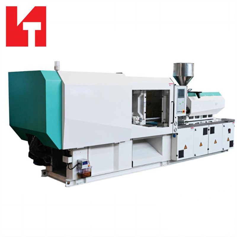
If internal troubleshooting hits a wall, do not accept continuous scrap generation. Partnering with an OEM for dedicated technical support is highly cost-effective compared to wasting premium resins. Ultimately, investing in a modern, purpose-built medical injection molding machine ensures long-term compliance, process stability, and profitability.
Sustainable defect resolution requires stepping away from isolated parameter tweaks. You must analyze the holistic interaction between the material flow, the tool integrity, and the machine capability. Relying on guesswork puts your regulatory compliance and patient safety in jeopardy.
Adopt a decoupled molding approach to control the plastic predictably. Always verify your machine capacity limits before fighting stubborn short shots. Audit your scrap rates regularly against machine age and tooling health. Recognizing when a tool needs maintenance or a machine needs replacing is a core engineering competency.
We encourage production and engineering teams to audit their current processing metrics honestly. Consult with engineering experts for technical support, comprehensive DFM analysis, or to evaluate advanced molding systems tailored specifically for high-precision medical applications.
A: A degraded check ring allows inconsistent amounts of plastic to leak backward over the screw during injection. This results in varying actual shot sizes despite locked machine settings. Some cycles push too little plastic (causing short shots), while others seal better and push too much (causing over-packing and flash).
A: Position-based switchovers account for mechanical lag and resin viscosity changes. This ensures the machine shifts to holding pressure at the exact same physical fill volume every single cycle. This method naturally compensates for equipment age and wear.
A: Yes. Over-clamping can crush micro-vents in a medical injection mould. This traps gas inside the cavity, leading to burn marks, short shots, and permanent tool damage. Flash should be fixed via pressure adjustments, temperature drops, or proper tool maintenance first.


